
Product
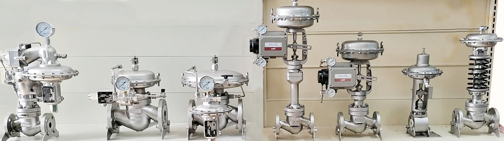
- Self-operated pressure control valve �� SP90H type Self-pressure regulating valve �� SP429 Small Flow Self-Operated Micro-Pressure Regulating Valve �� SP592 Commander Self-Operated Micro-Pressure Valve �� SP3000 Self-Operated Single-Base Pressure Regulating Valve �� SP4000 Self-Operated Cage Pressure Regulating Valve �� SP9000 Bellows-balance Self-operated Pressure Regulator
Contact
- Tel:+86-021-69673386
- Fax:+86-021-59332733
- Address: Shanghai for construction of development zone
SP90H type Self-pressure regulating valve
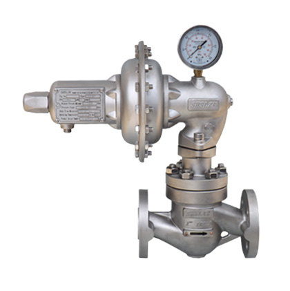
Product overview
SP90H type pressure regulating valve is a direct effect of spring set general type pressure regulating valve, only for the pressure control valve, gas can be applied to various types of low corrosion and low viscosity liquid. The minimum control pressure of 3Kpa, the highest control pressure is 1500Kpa, the minimum temperature of -48 ��, the highest temperature of 120 ��.
Features
��Compact structure--- the embedded spring structure makes the pressure regulating valve more compact and well protected.
��with pressure gauge pressure gauge adjustment -- standard pressure valve for type SP90H, the field installation and adjustment is more convenient.
��safety overload -- self-operated pressure regulating valve in the use of process pressure overload is inevitable, the result is often caused by damage to the valve, leakage or other accidents. SP90H adjustable overload protection mechanism of pressure valve can make the pressure regulating valve safe bearing is higher than the voltage range limit severalfold even a few times overload pressure, nominal pressure some configuration can achieve the valve completely.
�� no filler -- stem is often the main parts of the external leakage of valve, SP90H type adjustable without packing structure makes the valve stem valve without leakage may.
��convenient voltage regulation -- screw adjusting mechanism makes the pressure more easy, convenient, fast.
��Easy installation--- the field pipeline and installation space can not be expected when the valve is outputted, it is not convenient to calibrate and watch the pressure regulating valve due to influences from the surrounding devices after installation. The executor and regulation device of the SP90H pressure regulating valve can rotate by 3600 under non-disassembled state and old performance parameters are not affected after adjustment.
��pressure difference actuator using leverage -- Thrust amplification regulator, the regulator has higher differential pressure.
��off -- a lever boosting mechanism can effectively increase the closing force, so that it has more superior turn-off performance.
�� low leakage -- single-seat valve in the closed valve leakage is very small, soft seal spool can completely shut off the flow, make the system in the state of pressure keeping.
�� Stainless actuator - as an important part of the regulator, the actuator is made of stainless plate to ensure its high pressure-resistance and long service life.
��Easy maintenance- the selection criteria of the every structure of the SP90H regulator is to make sure the most convenient installation and maintenance while ensuring the performance requirements are met.
The top-mounted push-down installation method allows you to inspect and maintain the internal parts without any special tools before disassembling the regulator.
avoid all unnecessary repeat matching operation. The internal part has sufficient clearance to make sure itself can be easily taken out or put in. The dissembling of the internal parts can be easily performed even the carton steel regulator rusts after long-term operation.
��Universal parts – SP90H regulator has extremely high parts universality with the whole self-operated products series manufactured by our company. It helps to reduce the inventory of spare parts.
Body size��performances
��Body size (flanged connection)
DN15��1/2”���� DN20��3/4”���� DN25��1”���� DN40��11/2”���� DN50��2”��
�� Pressure ratings
PN16��40��64 ANSI 150LB��300LB��600LB��Other grade standard can be customized��
��Flow coefficient
| Diameter of valve base | 2 | 4 | 6 | 8 | 10 | 12 | 14 | 18 | 22 |
| Full open KV of valve core | 0.1 | 0.3 | 0.6 | 1 | 1.6 | 2.5 | 4.5 | 6.5 | 10 |
| Operation KV | 0.1 | 0.3 | 0.5 | 0.8 | 1.2 | 1.8 | 2.5 | 3.3 | 5 |
Remark :DN15 KV 4.5, DN20 KV 6.5, the diameter is not restricted.
��In order to ensure the voltage accuracy in calculation, selection by the use of KV, in consideration of the valve in the fault condition of the maximum flow rate according to the full KV.
��Feedback interface
ZG1/4��10mm union connector is provided in the plant. 10mm weld-end connector will be provided if the control pressure is over 2.0Mpa.
��Pressure measuring method
The valve outside pressure, the valve pressure or body flange taps.
��Operating temperature
For the soft-sealing valve, depends on the materials of the seals and diaphragm.
NBR -29��-82��
FKM -8��-120��
SR -48��-85��
EPDM -38��-115�� PTFE -40��-120��
For the seal valve because the valve for the installation of isolation tank, the use of temperature depends directly on the membrane using temperature.
��Leak-proof grade
Soft-sealing VI
Hard-sealing 0.003% x rating capacity of valve
��Closing grade <8% of upper limit of regulation range
��Regulation range, actuator configuration, differential pressure, accuracy
| Executor number | Spring number | Pressure regulation scope Kpa | precision: upper limit of %X pressure regulation scope | Maximum withstanding pressure of executor Kpa | ||||||||
| 2 | 4 | 6 | 8 | 10 | 12 | 14 | 18 | 22 | ||||
| 02.01.00 | HS016 | 65-200 | 6.5/2% | 6.5/4% | 6.5/6% | 5.6/7% | 3.5/8% | 2.5/9% | 1.8/9% | 1.1/9.5% | 0.7/11% | 3200 |
| HS017 | 120-360 | 6.5/2% | 6.5/4% | 6.5/6% | 6.5/7% | 6.2/8% | 4.5/9% | 3.3/9% | 2.1/10% | 1.3/12% | ||
| HS018 | 150-460 | 6.5/2% | 6.5/6% | 6.5/8% | 6.5/9% | 6.5/10% | 5.6/11% | 4.2/11% | 2.6/12% | 1.7/15% | ||
| HS019 | 240-720 | 6.5/3% | 6.5/6% | 6.5/8% | 6.5/9% | 6.5/10% | 6.5/12% | 5.3/12% | 3.2/14% | 2.1/15% | ||
| 02.02.00 | HS014 | 9-28 | 6.5/2% | 6.2/3% | 2.7/5% | 1.5/5% | 0.9/6% | 0.7/7% | 0.5/7% | 0.3/7% | 0.2/9% | 2500 |
| HS015 | 17-54 | 6.5/2% | 6.5/4% | 5.6/6% | 2.9/6% | 1.8/7% | 1.2/8% | 0.9/9% | 0.6/9% | 0.4/10% | ||
| HS016 | 33-100 | 6.5/2% | 6.5/4% | 6.5/6% | 5.6/7% | 3.5/8% | 2.5/9% | 1.8/9% | 1.1/9.5% | 0.7/11% | ||
| HS017 | 60-180 | 6.5/2% | 6.5/4% | 6.5/6% | 6.5/7% | 6.2/8% | 4.5/9% | 3.3/9% | 2.1/10% | 1.3/12% | ||
| HS018 | 75-230 | 6.5/2% | 6.5/6% | 6.5/8% | 6.5/9% | 6.5/10% | 5.6/11% | 4.2/12% | 2.6/12% | 1.7/15% | ||
| HS019 | 120-360 | 6.5/3% | 6.5/6% | 6.5/8% | 6.5/9% | 6.5/10% | 6.5/12% | 5.3/12% | 3.2/14% | 2.1/15% | ||
| 02.03.00 | HS013 | 3-9 | 6.5/3% | 4��1/3% | 1.8/4% | 1.0/5% | 0.6/5% | 0.4/6% | 0.3/6% | 0.2/6% | 0.15/8% | 2000 |
| HS014 | 5-14 | 6.5/2% | 6.2/3% | 2.7/5% | 1.5/5% | 0.9/6% | 0.7/7% | 0.5/7% | 0.3/7% | 0.2/9% | ||
| HS015 | 9-27 | 6.5/2% | 6.5/4% | 5.1/6% | 2.9/6% | 1.8/7% | 1.2/8% | 0.9/9% | 0.6/9% | 0.4/10% | ||
| HS016 | 17-50 | 6.5/2% | 6.5/4% | 6.5/6% | 5.6/7% | 3.5/8% | 2.5/9% | 1.8/9% | 1.1/9.5% | 0.7/11% | ||
| 02.09.00 | HS018 | 330-1000 | 6.5/2% | 6.5/6% | 6.5/8% | 6.5/9% | 6.5/10% | 5.6/11% | 4.2/11% | 2.6/12% | 1.7/15% | 3800 |
| HS019 | 500-1500 | 6.5/3% | 6.5/6% | 6.5/8% | 6.5/9% | 6.5/10% | 6.5/12% | 5.3/12% | 3.2/14% | 2.1/15% | ||
Remark :�� The theoretical precision indicates the theoretical pressure deviation of the valve under 10-70% openness and constant pressure difference. It will be affected by the pressure difference change and flow in actual application. The actual theoretical deviation is computed by the process parameter.
The flow feature of the pressure regulating valve approaches to linearity prior to 70% openness.
Structure, part list and part material
The pressure regulating valve consists of executor component and pressure regulating valve component which are connected as a whole via the connection nut.
part list and part material
SN Part name Material
01 onnection bush 304SS��316L
02 Retaining pin 304SS��316L
03 Connection pole 304SS��316L
04 Overload spring 304SS��316L
05 Screw cover 304SS��316L
06 End cover CF8��CF3M
07 Pin 304SS��316L
08 Connection bolt 304SS��316L
09 Drivepipe 304SS��316L
10 Down pin 304SS��316L
11 Shaft cover 304SS��316L
12 contact roller 304SS��316L
13 east Right lever 304SS��316L
14 Right lever 304SS��316L
15 Retaining ring 304SS
16 Press plate CF8
17 Guide bush 304SS��316L
18 Spring base 304SS, 316L
19 offsetting spring 304SS��316L
20 Valve cover WCB, CF8��CF3M
21 The limiting piece 304SS��316L
22 Valve rod 304SS��316L
23 bonnet gasket 316SS spiral wound graphite
316L spiral wound graphite
316L spiral wound PTFE
24 Spool ( soft seal ) 304SS��316L
25 screw 304SS, 316L
26 Valve cushion NBR��FKM��SR��PTFE
27 Bushing CF8��CF3M
28 Valve base 304SS��316L
29 valve seat gasket 316SS spiral wound graphite
316L spiral wound graphite
316L spiral wound PTFE
30 Valve body WCB, CF8��CF3M
31 Protection cover 304SS
32 Flag
33 Regulation screw 304SS
34 Cushion PTFE
35 Regulation nut HPb59-1
36 End cover CF8��CF3M
37 Limit ring 304SS
38 Pin 304SS
39 O-ring NBR
40 Left film cover 304SS��316L
41 Spring base 304SS
42 tray 08F
43 Film NBR��FKM��SR
44 Right film cover 304SS��316L
45 Hard sealing bead welding valve core 304SS��316L
46 Hard sealing bead welding valve base 304SS��316L
47 Hard sealing valve core 304SS��316L
48 Given spring 304SS��60Si 2MnA
B01 Internal hexagon screw 304SS, 316L
B02 O-ring NBR��FKM��SR
B03 O-ring NBR��FKM��SR
B04 Internal hexagon screw 304SS
B05 sealing-ring NBR, FKM, SR, PTFE
B06 Circlips for shaft 304SS��316L
B07 O-ring NBR��FKM��SR
B08 Hexagon nut 304SS
B09 stud bolt 304SS
B10 Internal hexagon screw 304SS
B11 sealing-ring NBR, FKM, SR, PTFE
B12 Circlips for shaft 304SS
B13 O-ring NBR��FKM��SR
B14 Internal hexagon screw 304SS
B15 Hexagon bolt 304SS
B16 Hexagon nut 304SS
B17 Hexagon nut 304SS
B18 spring gasket 304SS
Accessories and materials selection
��SP90H type pressure regulating valve for pressure control valve, valve seal type divided by soft sealing ( type 90H1), hard sealing (type 90H2 ), surfacing hard sealing ( type 90H3).
��The medium flows into the valve and flows out via the flow regulation of valve core and valve base. The after-valve pressure is brought into the executor film cavity and generates push. Compared to the given spring push, when this push is more than the spring force, the film component will drive the valve core to reduce the openness. On the contrary, when the push is less than the spring force, the openness of the valve core will increase, namely the after-valve pressure reduces and the openness of the valve core increases. The after-valve pressure increases and the openness of the valve core till the push is equal to the spring force. At this time, the valve core will keep the openness of the after-valve pressure and mass. At this time, this pressure is the set pressure of the pressure regulating valve. When the before-valve pressure or after-valve mass changes and leads to change to the after-valve pressure, the old balance will be damaged. The film component will drive the valve core for regulation and compensation and restore the pressure. On the whole, regardless of operation condition, the after-valve pressure will be always controlled within certain scope. When the after-valve flow reduces to “0”, the after-valve pressure will gradually increase till it exceeds the spring force to close the valve core. The after-valve pressure is under keep state. The level regulation device of the pressure regulating valve will effectively amplify push. If the pressure is higher than set value, it will close the pressure regulating valve tightly.
The set pressure depends on the ratio of the spring force and valid film area. For each installed pressure regulating valve, the valid film area is fixed and the spring force is adjustable. To rotate the regulation screw, you can adjust the pressure and the pressure meter of the pressure regulating valve will display after-valve pressure.
��soft seal ( 90H1 ) is the main sealing washer in the valve insert various types of material, can be tightly closed, but generally used for gas and liquid medium pressure difference.
Seal ( 90H2 ) and the hard alloy welding seal ( 90H3 ) is applied to the metal seal, high pressure liquid, use the higher differential pressure, differential pressure resistance welding hard alloy after better performance. But the hard sealing valve leakage trace when closed, should not be used to complete shutdown condition.
��pressure regulating valve installation direction must be consistent with the arrow on the valve body, the pressure regulating valve should be installed vertically, the repair and the maintenance are convenient, but the pressure regulator valve spool is small, compact structure, any installation does not affect its performance.
��pressure regulating valve should be installed before and after the cut-off valve, so that the repair and maintenance, installation of bypass valve should be in the application of important, for emergency use. The valve can not install pressure gauge, pressure regulating valve is self-contained, but also should be installed on the valve before the pressure gauge.
��for valve pressure and the valve body flange pressure regulating valve can be installed directly in the pipeline.
��for should be installed pipe external pressure of the pressure regulating valve, a pressure guiding pipe should be installed on the valve or valve, pipe should be 10DN of the valve, the pressure point in 60DN, valve after the expansion tube should be based on expanding the diameter shall prevail.
��Leakage in the pressure regulating valve diaphragm damage causes the media, for the field does not allow leakage of medium, the pressure regulating valve actuator connected drainage to safe area.
��When it is not convenient to regulate and watch the installed pressure regulating valve at the field or the pressure regulating valve collides with other devices, to loosen the connection screw, the executor can wholly rotate in 3600. When a proper installation position is identified, you should screw up it without need of disassembling the valve and making any adjustment.
As for the body flange to determine the installation position of the best actuator pressure before ordering, or regulator of implementation of the site also need to install a pressure guiding pipe.
��The tube should have been cleaned or blown prior to installation of the pressure regulating valve. Particles and welding residues are not allowed.
��adjustable pressure valve installed for the test pressure of pipeline, should guide pressure ball valve pipe or valve closed, internal feedback pressure regulating valve should be removed the pressure regulating valve and pipeline pressure test.
Warning
As the pressure regulating valve to the scene to carry out the pressure test to it, must be aware of the pressure regulating valve is different from the ordinary valve, nominal pressure can not be the body as the standard, to take the pressure regulating valve pressure test pressure shall not exceed the maximum voltage of actuators, the body flange pressure and external pressure regulating valve valve assembly according to the nominal pressure test pressure, actuator according to their maximum allowable pressure. After pressure test executor should not any residual liquid, the pressure test should remove the downward pressure on the gauge pressure valve.
Operation
��Check whether different parts are installed correctly prior to operation.
��To open the ball valve or check valve on the pressure guide tube, first close the bypass valve (if provided), open the after-valve check valve, guarantee that the after-valve system has certain flow, slowly open the before-valve check valve and watch the pressure indicator, if no exception occurs, you can fully open the before-valve check valve, the pressure regulating valve enters operation state. To close its output pressure, you should open the protection cover on the executor and rotate the adjusting screw. To rotate clockwise, the pressure will increase. On the contrary, the pressure will reduce.
��seal pressure regulating valve for leakage trace, such as long-term disabled, should close the valve before the valve.
Key points for inspection & maintenance
��The internal pressure of the regulator must be completely released and separated with operating system whenever the disassembly of the regulator will be performed.
��The actuator and regulator are separate components that can be inspected and serviced individually after detaching.
��In any case, before the executor is disassembled, you should first rotate the adjusting screw in anti-clock direction, fully loosen the spring and disassemble it.
��stem demolition notice don't loosen the nut valve cover, the upper cover in the pressed state won't turn.
��The internal parts of the regulator are fixed with the compression of the upper bonnet. All internal parts can be removed after the removing of the bonnet.
��actuator diaphragm assembly reload shall ensure that their travel at about 10mm.
After the film component is connected with the connection bolt, you should rotate it inward to press the film component till the bottom and push out. You should feel that the valve core is just closed. At this time, the stroke of the film component should be about10mm.
Description on the nameplate
��Model
��Nominal diameter
��Nominal pressure
��Material of body/internal parts
��Material of diaphragm
��Regulation range
��Maximum pressure of regulator
��KV valve
��Operating temperature
��Flange standard
��Serial number
Selection criteria
��Pipeline dimensions
��Medium type
��Medium temperature, ambient temperature
��Medium density
��Upstream pressure, downstream pressure
��Flow rate
��Pressure measuring method
��Setting pressure
��Flange standard
��Requirements on material of the body and internal parts
��Other special requirements
| Nominal diameter | DN15(1/2”) | DN20(3/4”) | DN25(1”) | DN40(11/2”) | DN50(2”) | ||
|
L |
PN16(150lb) | 181 | 181 | 184 | 222 | 254 | |
| PN40(300lb) | 181 | 194 | 197 | 235 | 267 | ||
| PN64(600lb) | 206 | 206 | 210 | 251 | 286 | ||
| H1 | 186 | 186 | 196 | 212 | 216 | ||
| weight Kg | PN16(150lb) | 11 | 12 | 13 | 18 | 21 | |
| PN40(300lb) | 11 | 12 | 13 | 18 | 21 | ||
| PN64(600lb) | 12 | 15 | 17 | 22 | 25 | ||
Note: the weight of the actuator configuration varies, the weight is the average weight.
| Executor number | A |
| 02.01.00 | 157 |
| 02.02.00 | 191 |
| 02.03.00 | 233 |
| 02.09.00 | 157 |
Experience sharing
��After-valve security device
You must carefully evaluate the security and pressure withstanding of the after-valve devices. The before-valve maximum pressure may fully reach the before-valve pressure under exceptional case. In this case, it will damage or endanger the downstream device. The downstream should be installed with the security valve or other security relief device. The jump pressure of the security valve should be higher than the set pressure of the pressure regulating valve. Generally it is 30% higher than the control pressure of this pressure regulating valve. The drainage capacity of the security valve is computed as the full open KV of the pressure regulating valve. If necessary, the full open drainage capacity of the bypass valve should also be considered.
��Computing of flow factor and KV selection
The flow factor is computed as the common pressure regulating valve, it is described in detail. For KV selection, you should notice that the maximum valve openness should not be over 70%. The ideal openness range is 10-60%. The pressure regulating valve is a lever regulation device. KV is sleeted by used KV.
��Control instability:
The main instability condition happens with there is continuous equal-amplitude oscillation that can not be attenuated naturally. The reasons include the small capacity of the system or the small openness of the regulator. But these reasons are not always apply. Some system can be stably controlled with openness under 1%. The main cause of the instability is the amplification factor of the system is too large. The instability is difficult to be predicted. Instability can be normally eliminated with the gradually closing of the valve on the pressure introduction piping. If the instability can not be eliminated with this method, suitable valve seat diameter or KV value should be reselected.
The blocking of the regulator caused by foreign matters will also case oscillation. It can only be removed with maintenance.
��Selection of pressure measuring method
Pressure tapping mode field pipeline pressure, the valve body flange pressure, valve pressure. The pipeline pressure with high accuracy, but the trouble of installation, the valve pressure and the valve body flange taps are easy to install, for small flow valve selection valve in the pressure, choose the larger flow of flange of the valve body pressure, greater flow to select the line pressure. But in general the caliber of the valve and the valve diameter is same, can consider the use of the valve the pressure or the valve flange.
For reducing ratio of the valve or valve after the pressure control valve shall be selected for extremely low body flange taps or pipeline pressure.
For differential pressure and flow is large and the control pressure and very low valve (below 10Kpa) not only to calculate the valve flow capacity, but also estimate the flow capacity of the pipeline under low pressure after decompression valve, said valve is necessary to be expanding, this type of valve should choose the pipeline pressure.
��Selection of regulation range
The regulation range selected must cover the process settings required. There will be a number of regulation ranges can be used for the same setting value. The ranges should be selected to make the setting value is at the middle or upper middle of the range. It is because that the theoretical deviation of every combination of spring and actuator is fixed. The deviation will be smaller when the setting value is closer to the upper limit of the regulation range. Generally, it is suitable to make the setting valve is in the 50%-85% of the regulation range.
��Selection of actuator
Must be aware of the pressure regulating valve is different from ordinary control valve, the media will directly enter the actuator and the membrane contact, so we must consider whether the corrosion medium diaphragm, medium temperature exceeds the allowable temperature of the diaphragm, thereby choosing diaphragm material suitable.
��Selection of spool
�� Soft sealing is the primary selection for the sealing of the spool.The corrosion on the sealing gasket caused by the medium and the operational temperature range of the sealing gasket should also be evaluated. The hard-sealing spool should be selected for high temperature conditions. The spool and seat sealed with hard alloy bead welding have better high temperature performance. The hard sealing should also be selected when the differential pressure under normal temperature is larger than 1.5 Mpa. Soft sealing can be selected for gas medium.
SP5000 self-operated low pressure pressure relief valve | SC2000 pneumatic regulating valve | SP100H internal setting self-operated pressure regulating valve | SP8000 bellows sealed pneumatic regulating valve | SP9000 Bellows-balance Self-operated Pressure Regulator | SP4000 Self-Operated Cage Pressure Regulating Valve | SP3000 Self-Operated Single-Base Pressure Regulating Valve | SP592 Commander Self-Operated Micro-Pressure Valve | SP429 Small Flow Self-Operated Micro-Pressure Regulating Valve | SP90H type Self-pressure regulating valve |